Slkor SL3763: A High-Efficiency 3-Cell Lithium Battery Charging Solution for Modern Electronics
Shenzhen Slkormicro Semicon Co., Ltd (www.slkoric.com) is backed by a core technical team originating from Tsinghua University. Driven by innovation in new materials, advanced manufacturing processes, and next-generation products, Slkor has mastered world-leading third-generation semiconductor silicon carbide (SiC) power device technology. As a high-tech enterprise integrating IC design, R&D, manufacturing, and global sales, Slkor delivers highly reliable semiconductor products along with comprehensive, application-level technical support to customers worldwide.
1.1 Name: Slkor SL3763 Three-Cell Lithium Battery Charging Solution
1.2 Applications: Backup battery systems, handheld electronics, portable industrial and medical instruments, power tools, and standalone battery chargers
2. Complete Charging Management for Three-Cell Lithium Batteries
Supports charging currents up to 4A and integrates over-voltage protection, ensuring safe, efficient, and stable charging performance for demanding applications.
2.1 Automatic Recharge
After charging is completed, if both the input power and battery remain connected, the battery voltage may gradually decrease due to self-discharge or load consumption. When the voltage drops to 95.5% of the constant-voltage threshold, the SL3763 automatically re-enters charging mode and initiates a new charging cycle. This intelligent recharge function helps keep battery capacity consistently above 80%, extending usable runtime.
When no battery is connected, the SL3763 charges the output capacitor to the constant-voltage level (or slightly higher) before stopping. As the BAT pin’s operating current slowly discharges the output capacitor, the BAT voltage falls to the recharge threshold, prompting the SL3763 to restart charging. This results in a sawtooth waveform at the BAT pin and a pulsed output signal indicating that no battery is present.
It is not recommended to connect a battery while the charger is operating, as this may lead to undefined states or a sudden inrush current into the battery.
2.2 Sleep Mode Battery Current
When the input voltage is removed or drops below the battery voltage, the SL3763 automatically enters sleep mode. In this state, the current flowing into the BAT and CSP pins is only approximately 9 μA (VBAT = 12 V), significantly reducing standby power consumption and preserving battery energy.
3. Application of the Slkor Brand in Solar-Powered Lighting
Slkor offers a complete, end-to-end solution for solar charging and lighting systems, covering voltage and current sensing, amplifiers with constant-current sources, multi-cell lithium battery charging management, a wide range of MOSFET drivers, and phototransistors. These solutions enable efficient energy harvesting, storage, and utilization in solar applications.
4. Typical Application of Slkor SL3763 in 3-Cell Lithium Battery Charging
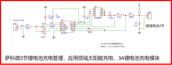
4.1 Application Principle:
The Slkor SL3763 charging IC efficiently stores solar energy in lithium batteries, enabling automatic day/night switching to form a compact and intelligent night-light driver module.
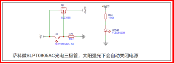
U8: The Slkor phototransistor (SLPT0805AC) conducts under sunlight, automatically shutting down the 5V supply. As a result, the Slkor SL348XT5 op-amp cannot drive the Slkor SL3400 MOSFET, keeping the lamp turned off during the day to save energy.
At night, U8 turns off, 5VCC is enabled, and the battery seamlessly powers the lamp board J2 — achieving fully automatic lighting control without manual intervention.
4.2 Figure 1: Slkor SL3763 lithium battery charging IC. Users can flexibly set the constant-current charging level according to the datasheet.
R1 = 40 mΩ → Charging current = 3 A (120 mV / 40 mΩ).
Slkor SL4435: P-channel MOSFET with Rds(on) = 30 mΩ @ Vgs = 4.5 V, Vds = 30 V, Id = 10 A. Ideal for high-side switching applications requiring low loss and high reliability.
SS56: Slkor Schottky diode with If = 5 A and Vr = 60 V, optimized for low-voltage rectification and high-efficiency power paths.
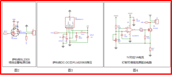
4.3 Figure 2: Slkor MOSFET SL2305S, Id = 4 A, Rds(on) < 45 mΩ @ Vgs = 4.5 V, SOT-23 package. Well-suited for switching applications and power path management in compact designs.
4.4 Figure 3: Slkor LM2596S-5.0 fixed 5 V DC-DC buck converter, Vin = 5–30 V, requiring minimal external components. Provides a stable and efficient power supply for system-level designs.
4.5 Figure 4: The lamp driver circuit uses the Slkor SL348XT5 op-amp (rail-to-rail input/output, low slew rate, up to 40 mA output) to directly drive the Slkor SL3400 MOSFET in a constant-current configuration. Lamp brightness can be easily adjusted via resistor R19.
Slkor SL3400 MOSFET: Vds = 30 V, Id = 5.8 A, SOT-23 package, Vgs(th) = 0.9 V. Optimized for low-voltage drive scenarios such as PWM control, power management, and load switching.
4.6 Figure 5: Under strong sunlight, the Slkor SLPT0805AC-LB1 phototransistor conducts, turning off Q7 and automatically disabling the solar lamp panel during the day to maximize energy efficiency.
Key Device: Slkor SLPT0805AC-LB1 infrared phototransistor — high sensitivity, compact SMD package, stable and reliable performance, energy-saving, and environmentally friendly. Widely used in light-controlled applications such as night lamps and solar lighting systems.
5. Slkor SL3763 Charging Demo Board


5.1 PCB Design Recommendations:
High-quality PCB layout is critical to fully unlocking the performance of the SL3763, minimizing EMI, and maximizing overall system efficiency. When designing the circuit shown in Figure 1, please pay special attention to the following best practices:
- The positive terminal of the input filter capacitor should be placed as close as possible to the source of the P-channel MOSFET to reduce input ripple and switching noise.
- Diode D1 should be positioned near the inductor, and the current-sense resistor should also be located close to the inductor to minimize high-current loop area.
- The output capacitor should be placed close to the current-sense resistor to ensure stable output and accurate current regulation.
- Keep all high-current traces between the input capacitor, P-MOSFET, D1, inductor, sense resistor, and output capacitor as short and wide as possible to reduce parasitic inductance and resistance.
- The GND and COM pin compensation component grounds must be connected directly to the system ground to prevent switching noise coupling. The input capacitor ground, D2 anode, and output capacitor ground should first connect to the same copper plane, and then return together to the system ground.
- The sense resistor R1 must be carefully placed so that the traces from the CSP and BAT pins are short, direct, and routed on the same PCB layer. CSP and BAT pins should connect directly to R1 to ensure high-accuracy current sensing and stable charging performance.
6. BOM Information of Slkor SL3763 Charging Demo Board


Comments
Post a Comment